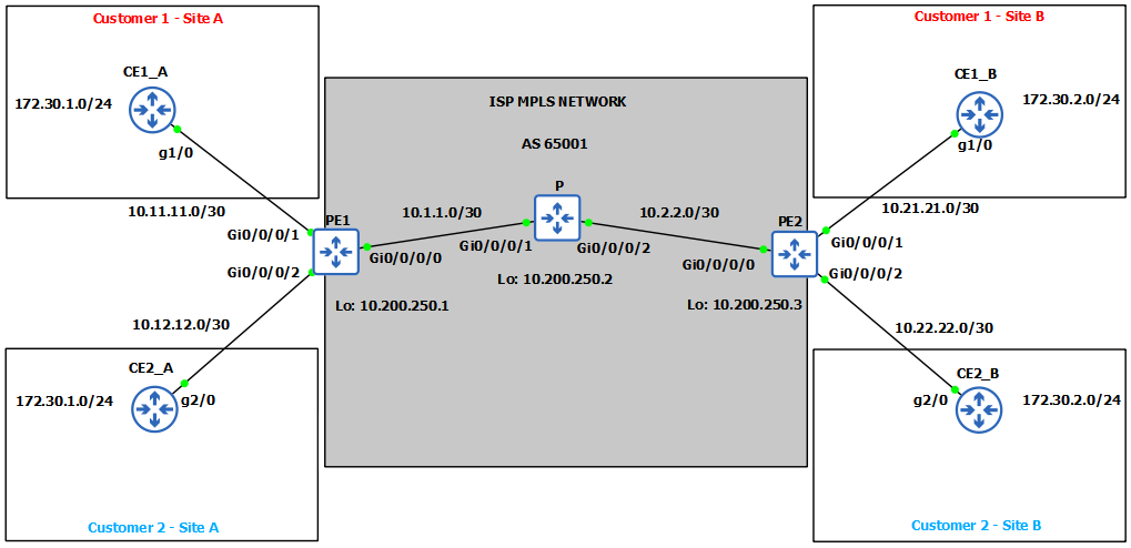
Continuing on from previous post, let’s start this one by configuring IGP protocol between PE and P routers so we can do LDP and BGP adjacencies over the underlay IGP, in our case we will use OSPF. Loopback interface will be used as peering address for all routers for BGP and LDP.
IGP configuration on P & PE Routers
1
2
3
4
5
6
7
8
9
10
11
12
13
14
15
16
17
18
19
20
21
RP/0/0/CPU0:PE1(config)#router ospf 1
RP/0/0/CPU0:PE1(config-ospf)#router-id 10.200.250.1
RP/0/0/CPU0:PE1(config-ospf)#area 0
RP/0/0/CPU0:PE1(config-ospf-ar)#interface gigabitEthernet 0/0/0/0
RP/0/0/CPU0:PE1(config-ospf-ar)#interface loopback 0
RP/0/0/CPU0:PE1(config-ospf-ar-if)#commit
-----
RP/0/0/CPU0:P(config)#router ospf 1
RP/0/0/CPU0:P(config-ospf)#router-id 10.200.250.2
RP/0/0/CPU0:P(config-ospf)#area 0
RP/0/0/CPU0:P(config-ospf-ar)#interface gigabitEthernet 0/0/0/1
RP/0/0/CPU0:P(config-ospf-ar)#interface gigabitEthernet 0/0/0/2
RP/0/0/CPU0:P(config-ospf-ar)#interface loopback 0
RP/0/0/CPU0:P(config-ospf-ar-if)#commit
-----
RP/0/0/CPU0:PE2(config)#router ospf 1
RP/0/0/CPU0:PE2(config-ospf)#router-id 10.200.250.3
RP/0/0/CPU0:PE2(config-ospf)#area 0
RP/0/0/CPU0:PE2(config-ospf-ar)#interface gigabitEthernet 0/0/0/0
RP/0/0/CPU0:PE2(config-ospf-ar)#interface loopback 0
RP/0/0/CPU0:PE2(config-ospf-ar-if)#commit
OSPF is up:
1
2
3
4
5
RP/0/0/CPU0:P#show ospf neighbor
Neighbor ID     Pri   State           Dead Time   Address         Interface
10.200.250.1    1     FULL/DR         00:00:34    10.1.1.1        GigabitEthernet0/0/0/1

10.200.250.3    1     FULL/DR         00:00:37    10.2.2.1        GigabitEthernet0/0/0/2
MP-BGP Configuration on PE routers
We mentioned before that MP-BGP enables BGP to carry special extension messages for different address families. MP-BGP will be used to carry customer’s prefixes across the MPLS network. MP-BGP is only configured between PE routers using loopback interface for peering which we advertised before via OSPF, BGP is not configured on P router.
When we configure MP-BGP we have to initialize vpnv4 address family in BGP general configuration, and also under the neighbor subconfiguration mode.
1
2
3
4
5
6
7
8
9
10
11
12
13
RP/0/0/CPU0:PE1(config)#router bgp 65001
RP/0/0/CPU0:PE1(config-bgp)#address-family vpnv4 unicast
RP/0/0/CPU0:PE1(config-bgp)#neighbor 10.200.250.3 remote-as 65001
RP/0/0/CPU0:PE1(config-bgp)#neighbor 10.200.250.3 update-source l0
RP/0/0/CPU0:PE1(config-bgp)#neighbor 10.200.250.3
RP/0/0/CPU0:PE1(config-bgp-nbr)#address-family vpnv4 unicast
-----
RP/0/0/CPU0:PE2(config)#router bgp 65001
RP/0/0/CPU0:PE2(config-bgp)#address-family vpnv4 unicast
RP/0/0/CPU0:PE2(config-bgp)#neighbor 10.200.250.1 remote-as 65001
RP/0/0/CPU0:PE2(config-bgp)#neighbor 10.200.250.1 update-source l0
RP/0/0/CPU0:PE2(config-bgp)#neighbor 10.200.250.1
RP/0/0/CPU0:PE2(config-bgp-nbr)#address-family vpnv4 unicast
As we can see , we have peering between PE1-PE2:
1
2
3
4
5
RP/0/0/CPU0:PE1#show bgp vpnv4 unicast neighbors
BGP neighbor is 10.200.250.3
 Remote AS 65001, local AS 65001, internal link
 Remote router ID 10.200.250.3
  BGP state = Established
Now when we configured peering between PE devices, we have to configure VRFs under the BGP ipv4 address family and give them Route Distinguisher RD which we talked about in Introduction post. RD is added on the PE router to customer’s network prefix to distinguish that same route prefix with some other VRFs prefix. For example in our case PE1 router is announcing prefixes it received from Customer1 as 1:100:172.30.1.0/24 and from Customer2 as 1:200:172.30.1.0/24. RD for Customer 1 is 1:100 and for Customer2 it is 1:200 , and that is how routes are distinguished to which VRF the specific route belong. RD is carried along with a route via MP-BGP when exchanging VPN route with other PE routers.
We will also need to redistribute those routes we received from Customers into the BGP after that they will become vpnv4 routes with unique RD. Those route’s will exist in BGPvpnv4 table on PE routers, so we also need to redistribute them to EIGRP, that way the CE routers and Customers sites can receive each other’s routes.
1
2
3
4
5
6
7
8
9
10
11
12
13
14
15
16
17
18
19
20
21
RP/0/0/CPU0:PE1(config)#router bgp 65001
RP/0/0/CPU0:PE1(config-bgp)#vrf Customer1
RP/0/0/CPU0:PE1(config-bgp-vrf)#rd 1:100
RP/0/0/CPU0:PE1(config-bgp-vrf)#address-family ipv4 unicast
RP/0/0/CPU0:PE1(config-bgp-vrf-af)#redistribute eigrp 100
RP/0/0/CPU0:PE1(config-bgp)#vrf Customer2
RP/0/0/CPU0:PE1(config-bgp-vrf)#rd 1:200
RP/0/0/CPU0:PE1(config-bgp-vrf)#address-family ipv4 unicast
RP/0/0/CPU0:PE1(config-bgp-vrf-af)#redistribute eigrp 200
RP/0/0/CPU0:PE1(config-bgp-vrf-af)#commit
-----
RP/0/0/CPU0:PE2(config)#router bgp 65001
RP/0/0/CPU0:PE2(config-bgp)#vrf Customer1
RP/0/0/CPU0:PE2(config-bgp-vrf)#rd 1:100
RP/0/0/CPU0:PE2(config-bgp-vrf)#address-family ipv4 unicast
RP/0/0/CPU0:PE2(config-bgp-vrf-af)#redistribute eigrp 100
RP/0/0/CPU0:PE2(config-bgp)#vrf Customer2
RP/0/0/CPU0:PE2(config-bgp-vrf)#rd 1:200
RP/0/0/CPU0:PE2(config-bgp-vrf)#address-family ipv4 unicast
RP/0/0/CPU0:PE2(config-bgp-vrf-af)#redistribute eigrp 200
RP/0/0/CPU0:PE2(config-bgp-vrf-af)#commit
Let’s see the BGPvpnv4 tables after we’ve redistributed those networks:
1
2
3
4
5
6
7
8
9
10
11
12
13
14
15
16
17
18
19
20
21
22
23
24
RP/0/0/CPU0:PE1#show bgp vpnv4 unicast
BGP router identifier 10.200.250.1, local AS number 65001
Route Distinguisher: 1:100 (default for vrf Customer1)
*> 10.11.11.0/30      0.0.0.0                  0         32768 ?
*>i10.21.21.0/30      10.200.250.3             0    100      0 ?
*> 172.30.1.0/24      10.11.11.2         2570240         32768 ?
*>i172.30.2.0/24      10.200.250.3       2570240    100      0 ?
Route Distinguisher: 1:200 (default for vrf Customer2)
*> 10.12.12.0/30      0.0.0.0                  0         32768 ?
*>i10.22.22.0/30      10.200.250.3             0    100      0 ?
*> 172.30.1.0/24      10.12.12.2         2570240         32768 ?
*>i172.30.2.0/24      10.200.250.3       2570240    100      0 ?
-----
RP/0/0/CPU0:PE2#show bgp vpnv4 unicast
BGP router identifier 10.200.250.3, local AS number 65001
*>i10.11.11.0/30      10.200.250.1             0    100      0 ?
*> 10.21.21.0/30      0.0.0.0                  0         32768 ?
*>i172.30.1.0/24      10.200.250.1       2570240    100      0 ?
*> 172.30.2.0/24      10.21.21.2         2570240         32768 ?
Route Distinguisher: 1:200 (default for vrf Customer2)
*>i10.12.12.0/30      10.200.250.1             0    100      0 ?
*> 10.22.22.0/30      0.0.0.0                  0         32768 ?
*>i172.30.1.0/24      10.200.250.1       2570240    100      0 ?
*> 172.30.2.0/24      10.22.22.2         2570240         32768 ?
Alright, so as you can see we’ve successfully exchanged routes between PE1 and PE2 through MP-BGP. We still don’t have connectivity between sites which we will resolve shortly. First we need to do one more thing, currently only PE routers have those networks from two Customers site, we need to somehow forward those routes to Customers Site_A and Site_B. We will achieve that by redistributing BGP into EIGRP, that way customers will finally receive the routes between Site_A & Site_B.
1
2
3
4
5
6
7
8
9
10
11
12
13
14
15
16
17
18
19
RP/0/0/CPU0:PE1(config)#router eigrp EIGRP
RP/0/0/CPU0:PE1(config-eigrp)#vrf Customer1
RP/0/0/CPU0:PE1(config-eigrp-vrf)#address-family ipv4
RP/0/0/CPU0:PE1(config-eigrp-vrf-af)#redistribute bgp 65001
RP/0/0/CPU0:PE1(config)#router eigrp EIGRP
RP/0/0/CPU0:PE1(config-eigrp)#vrf Customer2
RP/0/0/CPU0:PE1(config-eigrp-vrf)#address-family ipv4
RP/0/0/CPU0:PE1(config-eigrp-vrf-af)#redistribute bgp 65001
RP/0/0/CPU0:PE1(config-eigrp-vrf-af)#commit
-----
RP/0/0/CPU0:PE2(config)#router eigrp EIGRP
RP/0/0/CPU0:PE2(config-eigrp)#vrf Customer1
RP/0/0/CPU0:PE2(config-eigrp-vrf)#address-family ipv4
RP/0/0/CPU0:PE2(config-eigrp-vrf-af)#redistribute bgp 65001
RP/0/0/CPU0:PE2(config)#router eigrp EIGRP
RP/0/0/CPU0:PE2(config-eigrp)#vrf Customer2
RP/0/0/CPU0:PE2(config-eigrp-vrf)#address-family ipv4
RP/0/0/CPU0:PE2(config-eigrp-vrf-af)#redistribute bgp 65001
RP/0/0/CPU0:PE2(config-eigrp-vrf-af)#commit
Now we can check Customers routing tables, ill only show Customer1 but it is same for Cust2.
1
2
3
4
5
6
7
8
9
CE1_A#show ip route eigrp

D        10.21.21.0/30 [90/3072] via 10.11.11.1, GigabitEthernet1/0
D EX     172.30.2.0/24 [170/131072] via 10.11.11.1, GigabitEthernet1/0
-----
CE1_B#show ip route eigrp

D        10.11.11.0/30 [90/3072] via 10.21.21.1, GigabitEthernet1/0
D EX     172.30.1.0/24 [170/131072] via 10.21.21.1, GigabitEthernet1/0
We’ve received routes alright, but we still don’t have connectivity between sites, why? Well because MP-BGP and vpnv4 routes utilize MPLS forwarding tables for transport, and we still didn’t configure MPLS, now it is time to do it.
MPLS & LDP Configuration on P & PE routers
After we enable MPLS in Provider’s network, customer’s traffic will be switched in MPLS network based on labels.
1
2
3
4
5
6
7
8
9
10
11
12
13
14
15
RP/0/0/CPU0:PE1(config)#mpls ldp
RP/0/0/CPU0:PE1(config-ldp)#router-id 10.200.250.1
RP/0/0/CPU0:PE1(config-ldp)#interface gigabitEthernet 0/0/0/0
RP/0/0/CPU0:PE1(config-ldp)#commit
-----
RP/0/0/CPU0:P(config)#mpls ldp
RP/0/0/CPU0:P(config-ldp)#router-id 10.200.250.2
RP/0/0/CPU0:P(config-ldp)#interface gigabitEthernet 0/0/0/1
RP/0/0/CPU0:P(config-ldp)#interface gigabitEthernet 0/0/0/1
RP/0/0/CPU0:P(config-ldp)#commit
-----
RP/0/0/CPU0:PE2(config)#mpls ldp
RP/0/0/CPU0:PE2(config-ldp)#router-id 10.200.250.3
RP/0/0/CPU0:PE2(config-ldp)#interface gigabitEthernet 0/0/0/0
RP/0/0/CPU0:PE2(config-ldp)#commit
Let’s confirm on P router that we have LDP neighborship with both PE1 & PE2:
1
2
3
4
5
6
RP/0/0/CPU0:P#show mpls ldp neighbor brief
Peer               GR  NSR  Up Time     Discovery   Addresses     Labels
                                        ipv4  ipv6  ipv4  ipv6  ipv4   ipv6
-----------------  --  ---  ----------  ----------  ----------  ------------
10.200.250.1:0     N   N    00:05:54    1     0     2     0     5      0
10.200.250.3:0     N   N    00:05:54    1     0     2     0     5      0
Now that we have confirmed that, let’s check out the MPLS Forwarding tables on all router’s:
1
2
3
4
5
6
7
8
9
10
11
12
13
14
15
16
17
18
19
20
21
22
23
24
25
26
27
28
29
30
31
32
33
34
35
36
RP/0/0/CPU0:PE1#show mpls forwarding

Local  Outgoing    Prefix             Outgoing     Next Hop        Bytes
Label  Label       or ID              Interface                    Switched
------ ----------- ------------------ ------------ --------------- ------------
24000  Pop         10.200.250.2/32    Gi0/0/0/0    10.1.1.2        7586
24001  24000       10.200.250.3/32    Gi0/0/0/0    10.1.1.2        6257
24002  Pop         10.2.2.0/30        Gi0/0/0/0    10.1.1.2        0
24003  Aggregate   Customer1: Per-VRF Aggr[V]   \
                                      Customer1                    1040
24004  Unlabelled  172.30.1.0/24[V]   Gi0/0/0/1    10.11.11.2      0
24005  Aggregate   Customer2: Per-VRF Aggr[V]   \
                                      Customer2                    0
24006  Unlabelled  172.30.1.0/24[V]   Gi0/0/0/2    10.12.12.2      0
-----
RP/0/0/CPU0:P#show mpls forwarding

Local  Outgoing    Prefix             Outgoing     Next Hop        Bytes
Label  Label       or ID              Interface                    Switched
------ ----------- ------------------ ------------ --------------- ------------
24000  Pop         10.200.250.3/32    Gi0/0/0/2    10.2.2.1        13903
24001  Pop         10.200.250.1/32    Gi0/0/0/1    10.1.1.1        14729
-----
RP/0/0/CPU0:PE2#show mpls forwarding
Local  Outgoing    Prefix             Outgoing     Next Hop        Bytes
Label  Label       or ID              Interface                    Switched
------ ----------- ------------------ ------------ --------------- ------------
24000  Pop         10.200.250.2/32    Gi0/0/0/0    10.2.2.2        7724
24001  Pop         10.1.1.0/30        Gi0/0/0/0    10.2.2.2        0
24002  24001       10.200.250.1/32    Gi0/0/0/0    10.2.2.2        7546
24003  Aggregate   Customer1: Per-VRF Aggr[V]   \
                                      Customer1                    0
24004  Unlabelled  172.30.2.0/24[V]   Gi0/0/0/1    10.21.21.2      1700
24005  Aggregate   Customer2: Per-VRF Aggr[V]   \
                                      Customer2                    0
24006  Unlabelled  172.30.2.0/24[V]   Gi0/0/0/2    10.22.22.2      0
Pay attention to P router’s MPLS forwarding table, Outgoing Label says PoP . That’s what we discussed in our Introduction MPLS blog post. Since the next hop from both sides of P router is LER (Label Edge Router) and there’s no more routers in MPLS path, our LER’s (PE) doesn’t need to inspect the inner label, only outer (VPN label).
INSPECTING LSP PATH & MPLS LABELS (Forwarding Plane)
After we’ve configured everything, it is time to test connectivity and see how MPLS uses labels for forwarding of traffic in Provider’s network.
In this picture we issued ping command from CE1_A to CE1_B and captured traffic on the link between PE1 – P routers. You can see the outer MPLS label is 24000, that’s what is used to reach P router as you can see the next-hop is P router. It is learned via the LDP (Label Distribution Protocol) and has a local significance. The inner VPN label is 24004, it is added by the PE1 router and it is used to identify the correct next-hop on PE2 router , meaning once packet arrives at PE2,it will check the VPN label and it will see what is next-hop for label 24004, which will point him into Customer1. Please note that inner label is kept untouched by the P router. Only the PE routers perform push or pop of the VPN labels. So VPN label as per our MPLS forwarding tables for Customer1 is 24004 and for Customer2 it is 24006.
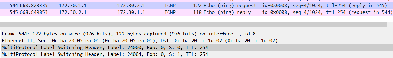
The P router is transit router it just swaps labels for the next-hop incase there’s more P routers, or it just pops labels (in our case it pops 24000 & 24001) as we’ve seen in the MPLS forwarding table above. This router takes the forwarding decision only based on labels. Label 24001 is label pushed by PE2 router when sending traffic to 10.200.250.1 (PE1). And Label 24000 is pushed by PE1 when sending traffic to 10.200.250.3 (PE2).
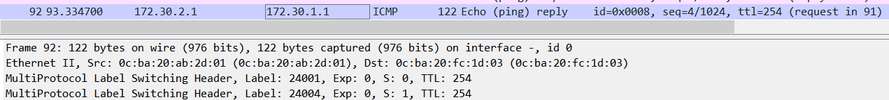
Now we will check the captured traffic on the link between P and PE2 to see what happened after icmp request packet went through P router. As you can see only one label remains (VPN label) because the P router has popped the label 24000. After that router PE2 removes the inner VPN header 24004 and forwards ICMP request as normal IP packet to CE1_B.
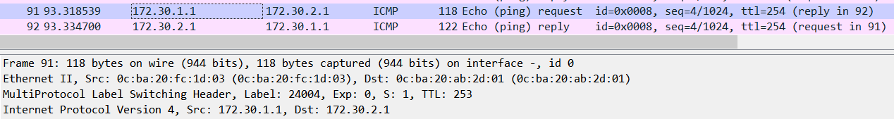
In the opposite direction, ICMP echo reply message from CE1_B to CE1_A carry also the same VPN label as the echo request because both sides are Customer1, and as you can see above MPLS forwarding table on PE2, label is same for Customer 1 as on PE1 router. And as you can see PE2 inserts the outer label 24001 when sending traffic to PE1 as we said before. The same process will happen as it did with echo request. P router will pop the outer label, and forward packet to PE1 which will check the VPN label and forward to appropriate Customer.
CHECKING CONTROL PLANE
In this picture we can see the BGP Update Message sent from PE1 to PE2. As you can see there is only one MPLS header with label 18, there’s no VPN label. When you expand then you can see VPN label inside the MP-BGP update message along with unique VPN-IPv4 prefix. The content is placed under the MP_REACH_NLRI path attribute.
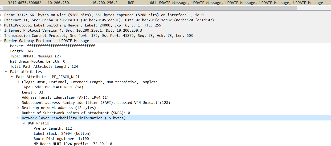
Here you can actually see how labels are carried with MP-BGP across the MPLS path.
MPLS L3VPNs have alot of moving parts that can be done differently depending on your topology or requirements. There’s many more information and configurations that can be done with MPLS, and i hoped i peaked your interest for you to research further.
Thank you for reading!