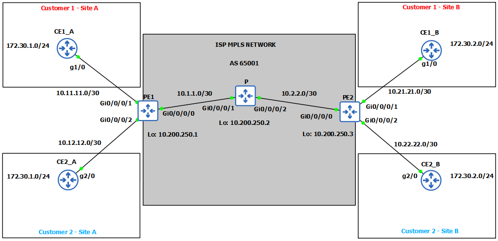
Our goal as we said previously in this lab is to connect remote customer sites so that they can communicate privately over the Service Providers network. This is where BGP/MPLS VPNs come in, separating traffic from both customers, using a combination of the VRF, MPLS and MP-BGP.
For our MPLS Core Network we will use Cisco router with IOS-XR software as it is mostly used as aggregation services routers on provider sites.
Let’s first create VRFs for our customers on PE routers. Customers’ forwarding tables are separated by using the VPN routing and forwarding table (VRF) on the PE router. Then we will define the RT attribute which will be carried across the MPLS network with MP-BGP to the other PE router which will use that attribute to check into which VRF it needs to import those incoming route updates. It is also called Route Leak.
PE1
1
2
3
4
5
6
7
8
9
10
11
12
13
14
15
16
| RP/0/0/CPU0:PE1(config)#vrf Customer1
RP/0/0/CPU0:PE1(config-vrf)#address-family ipv4 unicast
RP/0/0/CPU0:PE1(config-vrf-af)#import route-target 1:100
RP/0/0/CPU0:PE1(config-vrf-af)#export route-target 1:100
RP/0/0/CPU0:PE1(config)#int g0/0/0/1
RP/0/0/CPU0:PE1(config-if)#vrf Customer1
RP/0/0/CPU0:PE1(config-if)#ipv4 address 10.11.11.1 255.255.255.252
-------
RP/0/0/CPU0:PE1(config)#vrf Customer2
RP/0/0/CPU0:PE1(config-vrf)#address-family ipv4 unicast
RP/0/0/CPU0:PE1(config-vrf-af)#import route-target 1:200
RP/0/0/CPU0:PE1(config-vrf-af)#export route-target 1:200
RP/0/0/CPU0:PE1(config)#int g0/0/0/2
RP/0/0/CPU0:PE1(config-if)#vrf Customer2
RP/0/0/CPU0:PE1(config-if)#ipv4 address 10.12.12.1 255.255.255.252
RP/0/0/CPU0:PE1(config-if)#commit
|
PE2
1
2
3
4
5
6
7
8
9
10
11
12
13
14
15
16
| RP/0/0/CPU0:PE2(config)#vrf Customer1
RP/0/0/CPU0:PE2(config-vrf)#address-family ipv4 unicast
RP/0/0/CPU0:PE2(config-vrf-af)#import route-target 1:100
RP/0/0/CPU0:PE2(config-vrf-af)#export route-target 1:100
RP/0/0/CPU0:PE2(config)#int g0/0/0/1
RP/0/0/CPU0:PE2(config-if)#vrf Customer1
RP/0/0/CPU0:PE2(config-if)#ipv4 address 10.21.21.1 255.255.255.252
-------
RP/0/0/CPU0:PE2(config)#vrf Customer2
RP/0/0/CPU0:PE2(config-vrf)#address-family ipv4 unicast
RP/0/0/CPU0:PE2(config-vrf-af)#import route-target 1:200
RP/0/0/CPU0:PE2(config-vrf-af)#export route-target 1:200
RP/0/0/CPU0:PE2(config)#int g0/0/0/2
RP/0/0/CPU0:PE2(config-if)#vrf Customer2
RP/0/0/CPU0:PE2(config-if)#ipv4 address 10.22.22.1 255.255.255.252
RP/0/0/CPU0:PE2(config-if)#commit
|
After we did initial configuration we have to do peering with Customers so they can advertise us the networks they wish to be advertised through Service Providers network over to other Customers sites. In other words, so two Customer sites can communicate. We’ve chosen EIGRP as our peering protocol, you can choose any.
PE1
1
2
3
4
5
6
7
8
9
10
11
12
| RP/0/0/CPU0:PE1(config)#router eigrp EIGRP
RP/0/0/CPU0:PE1(config-eigrp)#vrf Customer1
RP/0/0/CPU0:PE1(config-eigrp-vrf)#address-family ipv4
RP/0/0/CPU0:PE1(config-eigrp-vrf-af)#autonomous-system 100
RP/0/0/CPU0:PE1(config-eigrp-vrf-af)#interface g0/0/0/1
-------
RP/0/0/CPU0:PE1(config)#router eigrp EIGRP
RP/0/0/CPU0:PE1(config-eigrp)#vrf Customer2
RP/0/0/CPU0:PE1(config-eigrp-vrf)#address-family ipv4
RP/0/0/CPU0:PE1(config-eigrp-vrf-af)#autonomous-system 200
RP/0/0/CPU0:PE1(config-eigrp-vrf-af)#interface g0/0/0/2
RP/0/0/CPU0:PE1(config-eigrp-vrf-af-if)#commit
|
PE2
1
2
3
4
5
6
7
8
9
10
11
12
| RP/0/0/CPU0:PE2(config)#router eigrp EIGRP
RP/0/0/CPU0:PE2(config-eigrp)#vrf Customer1
RP/0/0/CPU0:PE2(config-eigrp-vrf)#address-family ipv4
RP/0/0/CPU0:PE2(config-eigrp-vrf-af)#autonomous-system 100
RP/0/0/CPU0:PE2(config-eigrp-vrf-af)#interface g0/0/0/1
-------
RP/0/0/CPU0:PE2(config)#router eigrp EIGRP
RP/0/0/CPU0:PE2(config-eigrp)#vrf Customer2
RP/0/0/CPU0:PE2(config-eigrp-vrf)#address-family ipv4
RP/0/0/CPU0:PE2(config-eigrp-vrf-af)#autonomous-system 200
RP/0/0/CPU0:PE2(config-eigrp-vrf-af)#interface g0/0/0/2
RP/0/0/CPU0:PE2(config-eigrp-vrf-af-if)#commit
|
Now we will go ahead and configure EIGRP on Customer1 and 2 sides and bring up the neighborship. We will also redistribute the networks we want to get across Service Providers network to our other Sites or Branches. In our case it will be network 172.30.1.0/24 and 172.30.2.0/24 for both Customer1 and Customer2. We’re using the same network for demonstration purposes so you can see the power of MPLS L3VPNs and that customers can use the same overlapping address space.
CE1_A & CE1_B
1
2
3
4
5
6
7
8
9
10
11
12
13
14
15
| CE1_A(config)#int l0
CE1_A(config-if)#ip address 172.30.1.1 255.255.255.0
CE1_A(config-if)#int g1/0
CE1_A(config-if)#ip address 10.11.11.2 255.255.255.252
CE1_A(config)#router eigrp 100
CE1_A(config-router)#network 10.0.0.0
CE1_A(config-router)#redistribute connected
----------
CE1_B(config)#int l0
CE1_B(config-if)#ip address 172.30.2.1 255.255.255.0
CE1_B(config-if)#int g1/0
CE1_B(config-if)#ip address 10.21.21.2 255.255.255.252
CE1_B(config)#router eigrp 100
CE1_B(config-router)#network 10.0.0.0
CE1_B(config-router)#redistribute connected
|
CE2_A & CE2_B
1
2
3
4
5
6
7
8
9
10
11
12
13
14
15
| CE2_A(config)#int l0
CE2_A(config-if)#ip address 172.30.1.1 255.255.255.0
CE2_A(config-if)#int g2/0
CE2_A(config-if)#ip address 10.12.12.2 255.255.255.252
CE2_A(config)#router eigrp 200
CE2_A(config-router)#network 10.0.0.0
CE2_A(config-router)#redistribute connected
---------
CE2_B(config)#int l0
CE2_B(config-if)#ip address 172.30.2.1 255.255.255.0
CE2_B(config-if)#int g2/0
CE2_B(config-if)#ip address 10.22.22.2 255.255.255.252
CE2_B(config)#router eigrp 100
CE2_B(config-router)#network 10.0.0.0
CE2_B(config-router)#redistribute connected
|
Now we can see that the neighborship came up, and we can also check if we received Customers routes on our PE routers.
PE1
1
2
3
4
5
6
7
8
9
10
11
12
13
14
15
| RP/0/0/CPU0:PE1#show eigrp vrf Customer1 neighbors
IPv4-EIGRP VR(EIGRP) Neighbors for AS(100) VRF Customer1
H Address Interface Hold Uptime SRTT RTO Q Seq
(sec) (ms) Cnt Num
0 10.11.11.2 Gi0/0/0/1 12 00:26:41 16 200 0 2
RP/0/0/CPU0:PE1#show eigrp vrf Customer2 neighbors
IPv4-EIGRP VR(EIGRP) Neighbors for AS(200) VRF Customer2
H Address Interface Hold Uptime SRTT RTO Q Seq
(sec) (ms) Cnt Num
0 10.12.12.2 Gi0/0/0/2 11 00:22:17 1288 5000 0 3
|
1
2
3
4
5
6
7
8
9
10
11
| RP/0/0/CPU0:PE1#show route vrf Customer1
C 10.11.11.0/30 is directly connected, 01:56:42, GigabitEthernet0/0/0/1
L 10.11.11.1/32 is directly connected, 01:56:42, GigabitEthernet0/0/0/1
D EX 172.30.1.0/24 [170/2570240] via 10.11.11.2, 00:27:27, GigabitEthernet0/0/0/1
RP/0/0/CPU0:PE1#show route vrf Customer2
C 10.12.12.0/30 is directly connected, 01:57:21, GigabitEthernet0/0/0/2
L 10.12.12.1/32 is directly connected, 01:57:21, GigabitEthernet0/0/0/2
D EX 172.30.1.0/24 [170/2570240] via 10.12.12.2, 00:22:47, GigabitEthernet0/0/0/2
|
PE2
1
2
3
4
5
6
7
8
9
10
11
12
13
14
15
| RP/0/0/CPU0:PE2#show eigrp vrf Customer1 neighbors
IPv4-EIGRP VR(EIGRP) Neighbors for AS(100) VRF Customer1
H Address Interface Hold Uptime SRTT RTO Q Seq
(sec) (ms) Cnt Num
0 10.21.21.2 Gi0/0/0/1 12 00:27:09 40 240 0 2
RP/0/0/CPU0:PE2#show eigrp vrf Customer2 neighbors
IPv4-EIGRP VR(EIGRP) Neighbors for AS(200) VRF Customer2
H Address Interface Hold Uptime SRTT RTO Q Seq
(sec) (ms) Cnt Num
0 10.22.22.2 Gi0/0/0/2 13 00:23:44 16 200 0 2
|
1
2
3
4
5
6
7
8
9
10
| RP/0/0/CPU0:PE2#show route vrf Customer1
C 10.21.21.0/30 is directly connected, 00:38:43, GigabitEthernet0/0/0/1
L 10.21.21.1/32 is directly connected, 00:38:43, GigabitEthernet0/0/0/1
D EX 172.30.2.0/24 [170/2570240] via 10.21.21.2, 00:32:55, GigabitEthernet0/0/0/1
RP/0/0/CPU0:PE2#show route vrf Customer2
C 10.22.22.0/30 is directly connected, 01:25:35, GigabitEthernet0/0/0/2
L 10.22.22.1/32 is directly connected, 01:25:35, GigabitEthernet0/0/0/2
D EX 172.30.2.0/24 [170/2570240] via 10.22.22.2, 01:25:30, GigabitEthernet0/0/0/2
|
So far we’ve configured PE-CE peering, we’ve advertised networks from CE routers towards Service Provider routers, and now we can start configuring MPLS and BGP on Service Provider side to see how those networks are carried through the Service Providers Core all the way to Customers other sites and branches.
See you on the next write up and thank you for reading!