
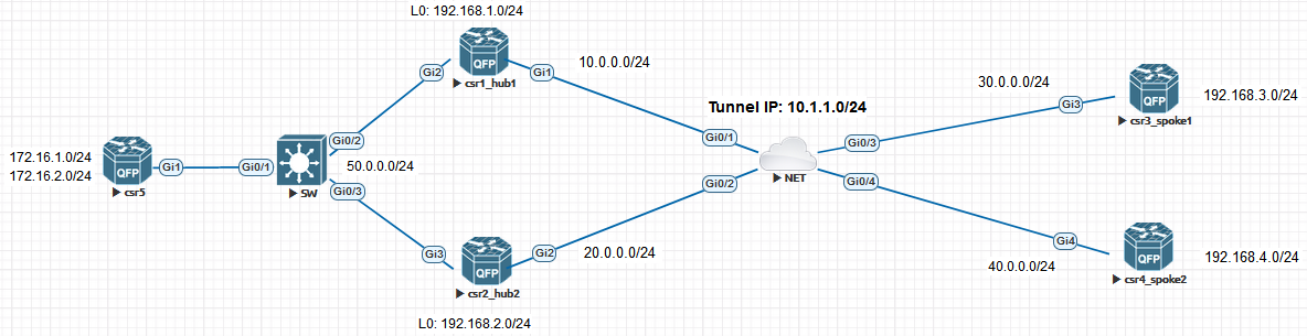
Dual HUB Single Cloud
HUB2 Configuration
Let’s bring up the second Hub by using similar config like on HUB1.
1
2
3
4
5
6
7
8
9
10
11
12
13
14
15
16
17
18
19
20
21
22
23
24
25
26
27
28
29
30
31
csr2_hub2(config)# interface Tunnel0
csr2_hub2(config-if)# ip address 10.1.1.2 255.255.255.0
csr2_hub2(config-if)# tunnel source GigabitEthernet2
csr2_hub2(config-if)# tunnel mode gre multipoint
csr2_hub2(config-if)# ip nhrp authentication test
csr2_hub2(config-if)# ip nhrp network-id 100
csr2_hub2(config-if)# ip nhrp map multicast dynamic
csr2_hub2(config-if)# tunnel key 100
csr2_hub2(config-if)# ip mtu 1400
csr2_hub2(config-if)# ip tcp adjust-mss 1360
csr2_hub2(config-if)# ip nhrp redirect
csr2_hub2(config-if)# tunnel protection ipsec profile IPSEC_PROFILE
------------------------------------------------
csr2_hub2(config)#router eigrp DMVPN
csr2_hub2(config-router)# address-family ipv4 unicast autonomous-system 1
csr2_hub2(config-router-af)# network 10.1.1.0 0.0.0.255
csr2_hub2(config-router-af)# network 192.168.2.0
csr2_hub2(config-router-af)# network 50.0.0.0
------------------------------------------------
csr2_hub2(config)#crypto isakmp policy 10
csr2_hub2(config-isakmp)# encr aes 256
csr2_hub2(config-isakmp)# hash sha256
csr2_hub2(config-isakmp)# authentication pre-share
csr2_hub2(config-isakmp)# group 5
csr2_hub2(config-isakmp)#crypto isakmp key test address 0.0.0.0
csr2_hub2(config)#crypto ipsec transform-set TSET esp-aes 256 esp-sha-hmac
csr2_hub2(cfg-crypto-trans)# mode transport
csr2_hub2(cfg-crypto-trans)#crypto ipsec profile IPSEC_PROFILE
csr2_hub2(ipsec-profile)# set transform-set TSET
csr2_hub2(ipsec-profile)#int tun0
csr2_hub2(config-if)#tunnel protection ipsec profile IPSEC_PROFILE
Now that the tunnels are up, we need to tell the spokes that they have another HUB to point to:
Spoke Config
1
2
3
4
5
csr3_spoke1#interface Tunnel0
csr3_spoke1(config-if)# ip nhrp nhs 10.1.1.2 nbma 20.0.0.1 multicast
---------------------------------------
csr4_spoke2#interface Tunnel0
csr4_spoke2(config-if)# ip nhrp nhs 10.1.1.2 nbma 20.0.0.1 multicast
Verification
We can verify that DMVPN peering came up:
1
2
3
4
5
6
7
8
csr2_hub2#show dmvpn
Interface: Tunnel0, IPv4 NHRP Details
Type:Hub, NHRP Peers:2,

 # Ent  Peer NBMA Addr Peer Tunnel Add State  UpDn Tm Attrb
 ----- --------------- --------------- ----- -------- -----
     1 30.0.0.1               10.1.1.3    UP 00:06:28     D
     1 40.0.0.1               10.1.1.4    UP 00:09:26     D
Now let’s check the routing table and traffic flow on spoke and see how the traffic is behaving.
1
2
3
4
5
6
7
8
9
10
11
12
csr3_spoke1#show ip route
D        172.16.1.0 [90/79365120] via 10.1.1.2, 00:54:29, Tunnel0
                    [90/79365120] via 10.1.1.1, 00:54:29, Tunnel0
D        172.16.2.0 [90/79365120] via 10.1.1.2, 00:54:29, Tunnel0
                    [90/79365120] via 10.1.1.1, 00:54:29, Tunnel0
D     192.168.1.0/24 [90/76800640] via 10.1.1.1, 00:54:29, Tunnel0
D     192.168.2.0/24 [90/76800640] via 10.1.1.2, 00:54:29, Tunnel0
      192.168.3.0/24 is variably subnetted, 2 subnets, 2 masks
C        192.168.3.0/24 is directly connected, Loopback0
L        192.168.3.1/32 is directly connected, Loopback0
D     192.168.4.0/24 [90/102400640] via 10.1.1.2, 00:54:29, Tunnel0
                     [90/102400640] via 10.1.1.1, 00:54:29, Tunnel0
We can see that now we have two routes to reach other spoke HUB1 and HUB2.
Let’s initiate traceroute to see the traffic behaviour:
1
2
3
4
5
6
7
8
csr3_spoke1#traceroute 192.168.4.1 source l0 numeric
Type escape sequence to abort.
Tracing the route to 192.168.4.1
VRF info: (vrf in name/id, vrf out name/id)
  1 10.1.1.2 41 msec
    10.1.1.1 11 msec
    10.1.1.2 17 msec
  2 10.1.1.4 25 msec *  19 msec
The traffic is being load balanced as we expected, until the direct tunnel is created with the spoke, and NHRP did its magic by overriding the next-hop to be the Tunnel-IP of the spoke. (The same behavior we seen in the last post about Phase3)
1
2
3
4
5
csr3_spoke1#traceroute 192.168.4.1 source l0 numeric
Type escape sequence to abort.
Tracing the route to 192.168.4.1
VRF info: (vrf in name/id, vrf out name/id)
  1 10.1.1.4 46 msec *  14 msec
1
2
3
4
5
6
7
8
9
csr3_spoke1#show ip nhrp
10.1.1.4/32 via 10.1.1.4
   Tunnel0 created 00:00:08, expire 01:59:51
   Type: dynamic, Flags: router nhop rib
   NBMA address: 40.0.0.1
192.168.4.0/24 via 10.1.1.4
   Tunnel0 created 00:00:08, expire 01:59:51
   Type: dynamic, Flags: router rib nho
   NBMA address: 40.0.0.1
CEF before and after:
1
2
3
4
5
6
7
8
 csr3_spoke1#show ip cef 192.168.4.0
192.168.4.0/24
  nexthop 10.1.1.1 Tunnel0
  nexthop 10.1.1.2 Tunnel0
 ---------------------------------------
 csr3_spoke1#show ip cef 192.168.4.0
192.168.4.0/24
  nexthop 10.1.1.4 Tunnel0
That is traffic behavior between Spokes. But what if you have some traffic at your HUB site. Maybe you don’t want to load balance because of the traffic flow,and some applications may be sensitive to that.
You gotta think about the path the packets will be taking when returning back to spoke from the HUB site. You may be dealing with asymmetric routing. There’s lot of design consideration to think about, and if you don’t have many requirements you can leave it at default load balance.
Let’s check the traffic flow to 172.16.1.0/24 and 172.16.2.0/24 networks:
1
2
3
4
5
6
7
8
csr3_spoke1#traceroute 172.16.1.1 source l0 numeric
Type escape sequence to abort.
Tracing the route to 172.16.1.1
VRF info: (vrf in name/id, vrf out name/id)
  1 10.1.1.2 44 msec
    10.1.1.1 17 msec
    10.1.1.2 11 msec
  2 50.0.0.5 30 msec *  38 msec
It’s being load balanced, we can also verify with CEF:
1
2
3
4
5
6
7
8
9
10
11
12
13
14
15
16
17
csr3_spoke1#show ip cef 172.16.1.0
172.16.1.0/24
  nexthop 10.1.1.1 Tunnel0
  nexthop 10.1.1.2 Tunnel0
-----------------------------------------------
csr3_spoke1#show ip cef 172.16.1.0 internal
172.16.1.0/24, epoch 2, RIB[I], refcnt 6, per-destination sharing
nexthop 10.1.1.1 Tunnel0, IP midchain out of Tunnel0, addr 10.1.1.1 7F091E1C9528
    path 7F092FC4C440, share 1/1, type attached nexthop, for IPv4
      nexthop 10.1.1.2 Tunnel0, IP midchain out of Tunnel0, addr 10.1.1.2 7F091E1C9340
      < 0 > IP midchain out of Tunnel0, addr 10.1.1.1 7F091E1C9528
              IP adj out of GigabitEthernet3, addr 30.0.0.2 7F0918BDB8D0
        < 1 > IP midchain out of Tunnel0, addr 10.1.1.2 7F091E1C9340
              IP adj out of GigabitEthernet3, addr 30.0.0.2 7F0918BDB8D0
        < 2 > IP midchain out of Tunnel0, addr 10.1.1.1 7F091E1C9528
              IP adj out of GigabitEthernet3, addr 30.0.0.2 7F0918BDB8D0
        < 3 > IP midchain out of Tunnel0, addr 10.1.1.2 7F091E1C9340
If you don’t want to load balance,and have one HUB as primary and other as Backup. You can summarize networks from HUB which you want to be the backup. The main HUB will advertise more specific routes and will remain the primary.
Example:
1
2
3
4
csr2_hub2(config)#router eigrp DMVPN
csr2_hub2(config-router)# address-family ipv4 unicast autonomous-system 1
csr2_hub2(config-router-af)# af-interface Tunnel0
csr2_hub2(config-router-af-interface)#summary-address 172.16.0.0/16
Check routing table and traceroute on Spoke:
1
2
3
4
5
6
7
8
9
10
11
12
csr3_spoke1#show ip route
***output ommited**
D        172.16.0.0/16 [90/79365120] via 10.1.1.2, 00:00:10, Tunnel0
D        172.16.1.0/24 [90/79365120] via 10.1.1.1, 00:00:10, Tunnel0
D        172.16.2.0/24 [90/79365120] via 10.1.1.1, 00:00:10, Tunnel0
------------------------------------
csr3_spoke1#traceroute 172.16.1.1 source l0 numeric
Type escape sequence to abort.
Tracing the route to 172.16.1.1
VRF info: (vrf in name/id, vrf out name/id)
  1 10.1.1.1 41 msec 17 msec 8 msec
  2 50.0.0.5 27 msec *  28 msec
Now it is only using primary HUB and it doesn’t load balance.
There’s lots of ways to play around with DMVPN this is just some example, it all depends on the design to meet your needs.
Thanks for reading!