
DMVPN
is an overlay hub and spoke transport technology where hub acts like centralized control plane leveraging the NHRP (Next hop resolution protocol) protocol which is used to register/map the spoke public IP with its tunnel ip, along with GRE protocol. NHRP is best understood when compared to ARP, it does almost the same thing except with tunnel ip instead of MAC addresses. In routers routing table next-hop will be the ip address of the tunnel not the outside address which GRE needs to use for encapsulation and sending of the traffic. That’s where NHRP jumps in, NHRP resolves the next-hop ip of the tunnel to the outside IP.
Since DMVPN is run over outside public transport we must combine it with IPsec for security reasons.
As we mentioned in the previous post the reasons why we use IPsec transport mode when GRE tunnel is used is because Tunnel mode is used for L2L (private subnets communication) where additional IP header is added for tunnel creation when there’s no GRE to do it.
Since we already have GRE adding additional header for transport, we don’t need tunnel mode. GRE encapsulation happens on the tunnel interface before the encryption.
Since GRE encapsulation along with IPsec adds additional overhead, much less when you use transport mode, you have to look out for MTU and TCP MSS. It is recommended to lower the MTU to 1400 on tunnel interface and TCP MSS to 1360 to avoid fragmentation.
Phase 1
DMVPN Phase 1 would be only p2p tunnel configuration between hub and spoke, where traffic from spoke to spoke have to travel through the hub. Meaning there’s no dynamic tunnel creation when the communication is initiated from one spoke to the other.
The difference in command between Phase1 and Phases2 is that we are specifying the tunnel destination in GRE configuration instead of using the command tunnel mode gre multipoint.
So we won’t waste time configuring Phase1 as the command difference is not big, let’s jump into Phase2 immediately.
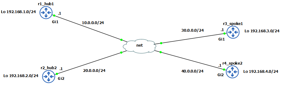
Outside IP addresses and loopbacks are pre-configured as per diagram.
Phase 2
HUB
1
2
3
4
5
6
7
8
9
10
r1_hub1(config)# interface Tunnel0
r1_hub1(config-if)# ip address 10.1.1.1 255.255.255.0
r1_hub1(config-if)# tunnel source GigabitEthernet1
r1_hub1(config-if)# tunnel mode gre multipoint
r1_hub1(config-if)# ip nhrp authentication test
r1_hub1(config-if)# ip nhrp network-id 100
r1_hub1(config-if)#ip nhrp map multicast dynamic
r1_hub1(config-if)#tunnel key 100
r1_hub1(config-if)# ip mtu 1400
r1_hub1(config-if)# ip tcp adjust-mss 1360
Here we specified that GRE tunnel will be multipoint meaning we allow dynamic tunnels to be created with spokes. We’ve specified what our nhrp network-id will be which is locally significant on each router it just identifies to which DMVPN cloud the tunnel interface belongs to, because multiple tunnels can belong to the same DMVPN cloud. The ip nhrp authentication is used obviously for authentication with the peers. Tunnel key is optional and it is used to identify the tunnel interface when there’s multiple tunnel interfaces using the same source interface. With ip nhrp map multicast dynamic we enable multicast support for NHRP so we can run routing protocols across the DMVPN which we will see later.
SPOKE
1
2
3
4
5
6
7
8
9
r3_spoke1(config)#interface tunnel0
r3_spoke1(config-if)# ip address 10.1.1.3 255.255.255.0
r3_spoke1(config-if)# tunnel source GigabitEthernet1
r3_spoke1(config-if)# tunnel mode gre multipoint
r3_spoke1(config-if)# ip nhrp nhs 10.1.1.1 nbma 10.0.0.1 multicast
r3_spoke1(config-if)# ip mtu 1400
r3_spoke1(config-if)# ip tcp adjust-mss 1360
r3_spoke1(config-if)# tunnel key 100
r3_spoke1(config-if)# ip nhrp network-id 100
To keep it clean ill only post one spoke, everything is the same on the other one except the ip address of the tunnel.
In summary what we did here is with command ip nhrp nhs 10.1.1.1 nbma 10.0.0.1 multicast we mapped the NHRP next-hop-server’s tunnel IP (nhs) address with its outside IP address (nbma) so nhrp can resolve it properly and point to the HUB and to allow multicast across. We also did a GRE multipoint mode so we can dynamically create tunnels with other spokes later on. That is the difference between Phase1 and Phase2.
Now we can use debug to see the registration with the hub:
1
2
3
4
r1_hub1(config)#debug nhrp
r1_hub1# NHRP: Receive Registration Request via Tunnel0
r1_hub1# Adding Tunnel Endpoints (VPN: 10.1.1.3, NBMA: 30.0.0.1)
r1_hub1# Successfully attached NHRP subblock for Tunnel Endpoints (VPN: 10.1.1.3, NBMA: 30.0.0.1)
And we can check to see that the tunnel is created, on Spoke it will show attribute as Static Tunnel because it is mapped and pointed to the HUB, but on HUB it will show Dynamic tunnel.
1
2
3
4
5
6
7
8
9
10
11
12
13
14
15
16
17
r1_hub1#show dmvpn
Interface: Tunnel0, IPv4 NHRP Details
Type:Hub, NHRP Peers:3,

 # Ent  Peer NBMA Addr Peer Tunnel Add State  UpDn Tm Attrb
 ----- --------------- --------------- ----- -------- -----
     1 30.0.0.1               10.1.1.3    UP 00:00:39     D
     1 40.0.0.1               10.1.1.4    UP 00:00:13     D
-------------------------------------------------------------------
r3_spoke1#show dmvpn
Interface: Tunnel0, IPv4 NHRP Details
Type:Spoke, NHRP Peers:2,

 # Ent  Peer NBMA Addr Peer Tunnel Add State  UpDn Tm Attrb
 ----- --------------- --------------- ----- -------- -----
     1 10.0.0.1               10.1.1.1    UP 00:01:58     S
     1 40.0.0.1               10.1.1.4    UP 00:00:04     D
Notice how the tunnels are both dynamic on HUB meaning they are brought up on demand, same like on one of the spokes after I initiated the icmp traffic from one spoke tunnel to the other, the tunnel shows up as dynamic.
And we can also see from NHRP perspective how it looks:
1
2
3
4
5
6
7
8
9
10
11
12
13
14
15
16
17
18
19
r1_hub1#show ip nhrp
10.1.1.3/32 via 10.1.1.3
   Tunnel0 created 00:02:28, expire 00:09:17
   Type: dynamic, Flags: registered nhop
   NBMA address: 30.0.0.1
10.1.1.4/32 via 10.1.1.4
   Tunnel0 created 00:00:17, expire 01:59:43
   Type: dynamic, Flags: unique registered nhop
   NBMA address: 40.0.0.1
----------------------------------------------------------------
r3_spoke1#show ip nhrp
10.1.1.1/32 via 10.1.1.1
   Tunnel0 created 00:00:08, never expire
   Type: static, Flags:
   NBMA address: 10.0.0.1
10.1.1.4/32 via 10.1.1.4
   Tunnel0 created 00:00:30, expire 01:59:29
   Type: dynamic, Flags: router implicit nhop
   NBMA address: 40.0.0.1
We can see on the HUB how nhrp mapped the tunnel ip (10.1.1.3 and 10.1.1.4) with the nbma outside address (30.0.0.1 and 40.0.0.1) of the spokes.
Now let’s bring up routing protocol neighborship on the tunnels and advertise networks across the DMVPN.
1
2
3
4
5
6
7
8
9
10
11
12
13
14
r1_hub1(config)#router eigrp DMVPN
r1_hub1(config-router)# address-family ipv4 unicast autonomous-system 1
r1_hub1(config-router-af)# network 10.1.1.0 0.0.0.255
r1_hub1(config-router-af)# network 192.168.1.0
------------------------------------------------------------------------------------
r3_spoke1(config)#router eigrp DMVPN
r3_spoke1(config-router)# address-family ipv4 unicast autonomous-system 1
r3_spoke1(config-router-af)# network 10.1.1.0 0.0.0.255
r3_spoke1(config-router-af)# network 192.168.3.0
------------------------------------------------------------------------------------
r4_spoke1(config)#router eigrp DMVPN
r4_spoke1(config-router)# address-family ipv4 unicast autonomous-system 1
r4_spoke1(config-router-af)# network 10.1.1.0 0.0.0.255
r4_spoke1(config-router-af)# network 192.168.4.0
We can see the neighborships are up and the hub received the routes:
1
2
3
4
5
6
7
8
9
10
11
12
13
14
15
16
17
r1_hub1#show ip eigrp nei
EIGRP-IPv4 VR(DMVPN) Address-Family Neighbors for AS(1)
H   Address                 Interface              Hold Uptime   SRTT   RTO  Q  Seq
                                                   (sec)         (ms)       Cnt Num
1   10.1.1.4                Tu0                      13 00:01:03   63  1398  0  3
0   10.1.1.3                Tu0                      11 00:02:30   18  1398  0  6
------------------------------------------------------------------------------------------------
r1_hub1#show ip route
S*    0.0.0.0/0 [1/0] via 10.0.0.2
C        10.0.0.0/24 is directly connected, GigabitEthernet1
L        10.0.0.1/32 is directly connected, GigabitEthernet1
C        10.1.1.0/24 is directly connected, Tunnel0
L        10.1.1.1/32 is directly connected, Tunnel0
C        192.168.1.0/24 is directly connected, Loopback0
L        192.168.1.1/32 is directly connected, Loopback0
D     192.168.3.0/24 [90/76800640] via 10.1.1.3, 00:22:33, Tunnel0
D     192.168.4.0/24 [90/76800640] via 10.1.1.4, 00:14:06, Tunnel0
What about the spokes did they receive routes?
1
2
3
4
5
6
7
8
9
r3_spoke1#show ip route
S*    0.0.0.0/0 [1/0] via 30.0.0.2
C        10.1.1.0/24 is directly connected, Tunnel0
L        10.1.1.3/32 is directly connected, Tunnel0
C        30.0.0.0/24 is directly connected, GigabitEthernet1
L        30.0.0.1/32 is directly connected, GigabitEthernet1
D     192.168.1.0/24 [90/76800640] via 10.1.1.1, 00:23:54, Tunnel0
C        192.168.3.0/24 is directly connected, Loopback0
L        192.168.3.1/32 is directly connected, Loopback0
They received only the network from the HUB, because there’s one important thing regarding EIGRP which we need to be careful about. It’s called split horizon it prevents us from advertising networks back out the interface we received it from. It is there to prevent routing loops. But since DMVPN is hub’n’spoke topology, we have to disable the split horizon on the tunnel interface of the HUB in order to advertise networks to other spokes.
1
2
3
4
r1_hub1(config)#router eigrp DMVPN
r1_hub1(config-router)#address-family ipv4 unicast autonomous-system 1
r1_hub1(config-router-af)#af-interface Tunnel0
r1_hub1(config-router-af-interface)#no split-horizon
After EIGRP did resync we can see that the network showed up on spokes:
1
2
3
4
5
6
7
8
9
10
r3_spoke1#show ip route
S*    0.0.0.0/0 [1/0] via 30.0.0.2
C        10.1.1.0/24 is directly connected, Tunnel0
L        10.1.1.3/32 is directly connected, Tunnel0
C        30.0.0.0/24 is directly connected, GigabitEthernet1
L        30.0.0.1/32 is directly connected, GigabitEthernet1
D     192.168.1.0/24 [90/76800640] via 10.1.1.1, 00:31:56, Tunnel0
C        192.168.3.0/24 is directly connected, Loopback0
L        192.168.3.1/32 is directly connected, Loopback0
D     192.168.4.0/24 [90/102400640] via 10.1.1.1, 00:31:21, Tunnel0
There’s one more problem to solve, in Phase2 we should have spoke-to-spoke connectivity, but notice that to get to r4_spoke2 network 192.168.4.0/24 we still have to traverse Tunnel0 through the HUB’s address 10.1.1.1. Traceroute shows us this:
1
2
3
4
5
r3_spoke1#traceroute 192.168.4.1 source l0 numeric
Tracing the route to 192.168.4.1
VRF info: (vrf in name/id, vrf out name/id)
  1 10.1.1.1 15 msec 17 msec 19 msec
  2 10.1.1.4 41 msec 40 msec 40 msec
Even though we have the dynamic tunnel up and running between spokes as we’ve seen above on the example, our traffic is still passing through the hub. It is because EIGRP has one more feature which is called next-hop-self. By default EIGRP modifies the next hop to itself, we have to disable that to receive the proper next-hop on spokes.
1
2
3
4
r1_hub1(config)#router eigrp DMVPN
r1_hub1(config-router)#address-family ipv4 unicast autonomous-system 1
r1_hub1(config-router-af)#af-interface Tunnel0
r1_hub1(config-router-af-interface)#no next-hop-self
And now routing table looks fine, we can see 192.168.4.0/24 being sent through 10.1.1.4 which is the tunnel address of r4_spoke2, and traceroutes verifies it.
1
2
3
4
5
6
7
8
9
10
11
12
13
14
S*    0.0.0.0/0 [1/0] via 30.0.0.2
C        10.1.1.0/24 is directly connected, Tunnel0
L        10.1.1.3/32 is directly connected, Tunnel0
C        30.0.0.0/24 is directly connected, GigabitEthernet1
L        30.0.0.1/32 is directly connected, GigabitEthernet1
D     192.168.1.0/24 [90/76800640] via 10.1.1.1, 00:07:12, Tunnel0
C        192.168.3.0/24 is directly connected, Loopback0
L        192.168.3.1/32 is directly connected, Loopback0
D     192.168.4.0/24 [90/102400640] via 10.1.1.4, 00:07:11, Tunnel0
---------------------------------------------------------------------------------
r3_spoke1#traceroute 192.168.4.1 source l0 numeric
Tracing the route to 192.168.4.1
VRF info: (vrf in name/id, vrf out name/id)
  1 10.1.1.4 74 msec 19 msec 21 msec
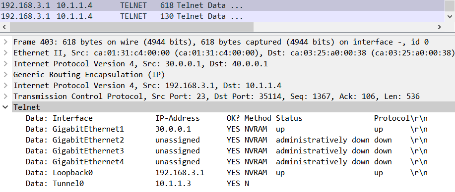
IPsec
Finally, this is why we need to protect the traffic with IPsec in order to avoid somebody sniffing our traffic. From the wireshark capture you can see how i telneted from r4_spoke2 to r3_spoke1 and i did a command „show ip int br“ and as you can see the results are displayed wide open.
1
2
3
4
5
6
7
8
9
10
11
12
13
14
15
16
17
18
19
20
21
22
23
24
25
r1_hub1(config)#crypto isakmp policy 10
r1_hub1(config-isakmp)# encr aes 256
r1_hub1(config-isakmp)# hash sha256
r1_hub1(config-isakmp)# authentication pre-share
r1_hub1(config-isakmp)# group 5
r1_hub1(config-isakmp)#crypto isakmp key test address 0.0.0.0
r1_hub1(config)#crypto ipsec transform-set TSET esp-aes 256 esp-sha-hmac
r1_hub1(cfg-crypto-trans)# mode transport
r1_hub1(cfg-crypto-trans)#crypto ipsec profile IPSEC_PROFILE
r1_hub1(ipsec-profile)# set transform-set TSET
r1_hub1(ipsec-profile)#int tun0
r1_hub1(config-if)#tunnel protection ipsec profile IPSEC_PROFILE
------------------------------------------------------------------------------------------------------
r3_spoke1(config)#crypto isakmp policy 10
r3_spoke1(config-isakmp)# encr aes 256
r3_spoke1(config-isakmp)# hash sha256
r3_spoke1(config-isakmp)# authentication pre-share
r3_spoke1(config-isakmp)# group 5
r3_spoke1(config-isakmp)#crypto isakmp key test address 0.0.0.0
r3_spoke1(config)#crypto ipsec transform-set TSET esp-aes 256 esp-sha-hmac
r3_spoke1(cfg-crypto-trans)# mode transport
r3_spoke1(cfg-crypto-trans)#crypto ipsec profile IPSEC_PROFILE
r3_spoke1(ipsec-profile)# set transform-set TSET
r3_spoke1(ipsec-profile)#int tun0
r3_spoke1(config-if)#tunnel protection ipsec profile IPSEC_PROFILE
Configuration is same on spoke2. One thing to note here we used address 0.0.0.0 meaning to match on any address so we can create dynamic tunnels without writing each remote spoke’s address making the configuration harder.
IPsec configuration was explained in the previous blog post so there’s no need to repeat it. Important thing is to match the encryption parameters and since we used IPsec Profile and not crypto maps, we apply the Profile to the tunnel interface with command tunnel protection ipsec profile .
Checking the IPsec tunnels are up and running with encryption:
1
2
3
4
5
6
7
8
9
10
11
12
13
14
15
r1_hub1#show crypto ipsec sa | i end|pkts
    #pkts encaps: 429, #pkts encrypt: 429, #pkts digest: 429
    #pkts decaps: 436, #pkts decrypt: 436, #pkts verify: 436
    #pkts compressed: 0, #pkts decompressed: 0
    #pkts not compressed: 0, #pkts compr. failed: 0
    #pkts not decompressed: 0, #pkts decompress failed: 0
    #send errors 0, #recv errors 0
     local crypto endpt.: 10.0.0.1, remote crypto endpt.: 40.0.0.1
    #pkts encaps: 422, #pkts encrypt: 422, #pkts digest: 422
    #pkts decaps: 410, #pkts decrypt: 410, #pkts verify: 410
    #pkts compressed: 0, #pkts decompressed: 0
    #pkts not compressed: 0, #pkts compr. failed: 0
    #pkts not decompressed: 0, #pkts decompress failed: 0
    #send errors 0, #recv errors 0
     local crypto endpt.: 10.0.0.1, remote crypto endpt.: 30.0.0.1
The tunnels are up and the wireshark is now showing traffic as encrypted and we can’t see the telnet traffic at all, only ESP (encapsulated security payload) packets which are hiding the information.
Thank you for reading!